News
Gable End Framing
Gable End Framing
Gable ends are a very common way to frame a building end and provide protection from the elements. Considering the load paths for both gravity loads and uplift forces is critical to avoid excessive deflection or lift off during a storm event.

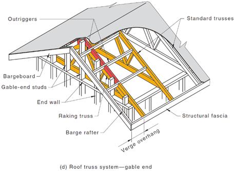
Figure 1 – AS1720.5 – Gable end
Gravity loads
To allow for the roof to cantilever past the end wall, the last couple of trusses are set down to allow outriggers to span perpendicular to the trusses and carry roofing and sheeting outside of the building limits. The outriggers are designed to carry their load width of roofing and sheeting. Their deflection is checked at design stage. Depending on the pitch, the outriggers closer to the heels may require to be multiple laminations. Their tributary area increases as the pitch decreases.
Depending on the batten type used and the overhang distance, blocking in between the outriggers may be required to avoid any sagging between the last truss and the barge rafter. These blocks will hold the roofing for both gravity loads and wind uplift forces. Proper considerations should be given when considering their connection details to the outriggers. Two skew nails may not be sufficient for high wind area or for heavy roofs.
Drilling screws in the end grain of the block through the outrigger is usually more adequate. End grain design consideration should be considered.
Finally, the structural fascia at the end of the trusses’ outriggers carries a portion of the cantilevered corner at the edge of the gable end, preventing it from sagging. Omitting this structural fascia would result in critical sag of the gable corner. Providing a standard sized element can also be detrimental if the element is under-designed.
When the gable end overhang is longer than the truss spacing, the reaction of the outriggers at the second truss in the building will be negative, which means that the outriggers will require to be tied down under gravity loads. It is critical to install the tie-downs before proceeding with the roofing.
Uplift forces
Under wind actions, the structure will experience both upward and downward actions. Downward actions shall be treated with the same load path as for gravity loads. For the upward actions, the suction starts at the outer shell of the building: the roofing. To start the load path, the roofing is fixed to the roof battens.
The battens are tied to the barge rafter at one end. The barge rafter, despite being fixed to the outriggers, it free to move up or down. Its position depends on the outriggers’ deflection. Having battens overlaid with outrigger is not mandatory. They may be fixed to blocks in between outriggers. The restrain of battens between the barge rafter and cut down truss depends then on the connection of the blocks in between outriggers. By extension, it depends on the outriggers.
For these two reasons specified above, the outriggers must be securely tied down to the cut down truss and following set down trusses. Truss manufacturing software will usually provide a detailed tie down schedule. The relevant Australian standards can be cross-referenced if needed.
But another problem looms ahead… how are the battens held down to the cut down truss and following set down trusses? In the best case, gable blocks would have been plated at manufacturing stage and tag plates would hold the blocks down to the cut down truss.
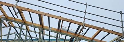
Figure 2 – Gable blocks plated to cut down trusses.
In many cases however, these gable blocks would be supplied loose, and they would be skew nailed to the truss. And what’s wrong with this empirical method, one may ask? Well, the restrain provided by 2 skew nail is not always enough, especially as overhangs are getting longer and optimisation pushes to use the very minimum grade of timber required for every element possible in the structure.
The next two pictures show both ends of a building after a storm event. While one end had not suffered any visible damage, the other was flipped. Inspection showed no gable blocks installed and no restrain of the outriggers.
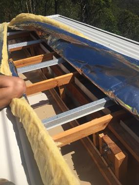
Figure 3 – Gable end blocks missing.
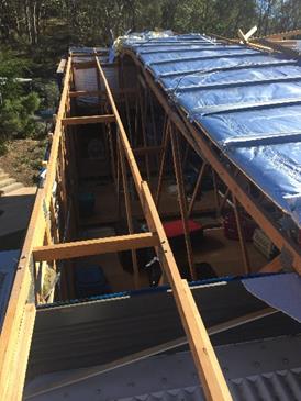
Figure 4 – Roofing upside down after a storm event.
A few options are offered for fabricators to assess properly the restrain required at the gable block location. You may want to use the standards as assess the loads based on AS1684.2. You may also prefer to contact your engineering team to provide you with the option best suited to your job. The use of G.I. strap with nails to the face of the gable block and to the face of the cut down top chord is usually a good direction to take, easy enough to install on site. Like with all wind actions, we won’t know until the structure is subject to its design actions…
Once outriggers and gable blocks are properly tied down, the relevant trusses should be tied down in accordance with their uplift reactions. All manufacturing software provide the relevant information.
Conclusion
While very broadly used and manufactured, the detailing involved in gable ends requires attention and special consideration. Outriggers must be designed with the relevant load width. Blocking must be included where the battens require. Gable blocks restrain to the cut down truss must be considered when supplied loose. If in doubt, always ask.
 Vaimiti Rigal
Structural Engineer
vaimiti.rigal@multinail.com
07 3297 3250
Let’s Work Together